WO2022038839A1 - 検査装置および導電率計 - Google Patents
検査装置および導電率計 Download PDFInfo
- Publication number
- WO2022038839A1 WO2022038839A1 PCT/JP2021/017326 JP2021017326W WO2022038839A1 WO 2022038839 A1 WO2022038839 A1 WO 2022038839A1 JP 2021017326 W JP2021017326 W JP 2021017326W WO 2022038839 A1 WO2022038839 A1 WO 2022038839A1
- Authority
- WO
- WIPO (PCT)
- Prior art keywords
- substrate
- wall portion
- measuring unit
- sample water
- electrode
- Prior art date
Links
- 238000007689 inspection Methods 0.000 title claims abstract description 43
- XLYOFNOQVPJJNP-UHFFFAOYSA-N water Substances O XLYOFNOQVPJJNP-UHFFFAOYSA-N 0.000 claims abstract description 99
- 239000000758 substrate Substances 0.000 claims abstract description 77
- 238000005259 measurement Methods 0.000 claims abstract description 33
- 238000012545 processing Methods 0.000 claims abstract description 6
- 230000005611 electricity Effects 0.000 abstract 2
- 238000000638 solvent extraction Methods 0.000 abstract 1
- 239000000523 sample Substances 0.000 description 68
- 238000000034 method Methods 0.000 description 17
- 238000010586 diagram Methods 0.000 description 8
- 239000007788 liquid Substances 0.000 description 7
- CURLTUGMZLYLDI-UHFFFAOYSA-N Carbon dioxide Chemical compound O=C=O CURLTUGMZLYLDI-UHFFFAOYSA-N 0.000 description 6
- 238000000354 decomposition reaction Methods 0.000 description 6
- 238000012856 packing Methods 0.000 description 6
- 239000005416 organic matter Substances 0.000 description 4
- 229910002092 carbon dioxide Inorganic materials 0.000 description 3
- 239000001569 carbon dioxide Substances 0.000 description 3
- 239000000463 material Substances 0.000 description 3
- 238000011144 upstream manufacturing Methods 0.000 description 3
- 238000001816 cooling Methods 0.000 description 2
- 230000001678 irradiating effect Effects 0.000 description 2
- 230000003647 oxidation Effects 0.000 description 2
- 238000007254 oxidation reaction Methods 0.000 description 2
- OKTJSMMVPCPJKN-UHFFFAOYSA-N Carbon Chemical compound [C] OKTJSMMVPCPJKN-UHFFFAOYSA-N 0.000 description 1
- 229910052799 carbon Inorganic materials 0.000 description 1
- 238000006243 chemical reaction Methods 0.000 description 1
- 239000003792 electrolyte Substances 0.000 description 1
- 150000002500 ions Chemical class 0.000 description 1
- 230000007257 malfunction Effects 0.000 description 1
- 238000012986 modification Methods 0.000 description 1
- 230000004048 modification Effects 0.000 description 1
- 230000001590 oxidative effect Effects 0.000 description 1
- 230000003071 parasitic effect Effects 0.000 description 1
- 239000000126 substance Substances 0.000 description 1
- 238000009279 wet oxidation reaction Methods 0.000 description 1
Images


Classifications
-
- G—PHYSICS
- G01—MEASURING; TESTING
- G01N—INVESTIGATING OR ANALYSING MATERIALS BY DETERMINING THEIR CHEMICAL OR PHYSICAL PROPERTIES
- G01N27/00—Investigating or analysing materials by the use of electric, electrochemical, or magnetic means
- G01N27/02—Investigating or analysing materials by the use of electric, electrochemical, or magnetic means by investigating impedance
- G01N27/04—Investigating or analysing materials by the use of electric, electrochemical, or magnetic means by investigating impedance by investigating resistance
- G01N27/06—Investigating or analysing materials by the use of electric, electrochemical, or magnetic means by investigating impedance by investigating resistance of a liquid
- G01N27/07—Construction of measuring vessels; Electrodes therefor
-
- G—PHYSICS
- G01—MEASURING; TESTING
- G01N—INVESTIGATING OR ANALYSING MATERIALS BY DETERMINING THEIR CHEMICAL OR PHYSICAL PROPERTIES
- G01N33/00—Investigating or analysing materials by specific methods not covered by groups G01N1/00 - G01N31/00
- G01N33/18—Water
- G01N33/1826—Organic contamination in water
- G01N33/1846—Total carbon analysis
Definitions
- the present disclosure relates to a conductivity meter for measuring the conductivity of sample water and an inspection device provided with the conductivity meter.
- the conductivity of the sample water may be measured as an index showing the properties of the sample water.
- the conductivity of the sample water is an index showing the ratio of the electrolyte dissolved in the sample water, and is used, for example, for measuring the amount of TOC (Total Organic Carbon) in the sample water.
- TOC Total Organic Carbon
- Patent Document 1 describes a measurement chamber for accommodating a sample volume to be irradiated with UV light, and a first measurement chamber located between the measurement chamber and the UV light source. Devices for measuring the conductivity of a liquid are disclosed, including a UV permeable window that seals and closes the sides. Patent Document 1 discloses that two measurement electrodes are etched so as to be in contact with a liquid existing in the measurement chamber. Further, Patent Document 1 describes that an electrode, which is a measurement electrode, is connected to a computer via a cable.
- the circuit that processes the detected values of the electrodes needs to be protected from contact with liquid.
- a method of protecting the circuit from liquid for example, as in the device described in Patent Document 1 in which the electrode and the computer are connected by a cable, the electrode and the circuit are connected by a cable, and the area that handles the liquid such as sample water is used. There is a way to pull the circuit apart.
- the cable connecting the electrode and the circuit becomes longer, noise is added to the detected value due to the influence of parasitic capacitance. Therefore, if the electrode and the circuit are connected by a cable, the accuracy of the conductivity meter will decrease.
- One of the purposes of this disclosure is to improve the accuracy of the conductivity meter provided in the inspection device for inspecting the sample water and to protect the electrical system of the inspection device.
- the inspection device of the present disclosure is an inspection device for inspecting sample water, and includes a housing, a wall portion having an opening that separates the inside of the housing into a first section and a second section, and sample water. It includes a conductivity meter for measuring the conductivity of the sample and an inflow tube for flowing sample water into the conductivity meter.
- the conductivity meter includes a measuring unit having an electrode unit arranged so as to be in contact with sample water, and a substrate on which a circuit for processing information output from the measuring unit is mounted. The measuring unit and the substrate are connected with the wall portion interposed therebetween.
- the measuring portion is arranged on the first surface of the wall portion on the first section side so that the electrode portion is located at the opening.
- the substrate is arranged on the second surface of the wall portion on the second compartment side so that the contact point for electrically connecting the electrode portion and the circuit is located at the opening portion.
- the conductivity meter of the present disclosure is a conductivity meter for measuring the conductivity of sample water, and processes a measuring unit including an electrode unit arranged so as to be in contact with the sample water and information output from the measuring unit. Includes a board on which the circuit to be mounted is mounted.
- the measuring unit and the substrate are connected with a wall portion that separates the inside of the housing into the first section and the second section.
- the measuring portion is arranged on the first surface of the wall portion on the first section side so that the electrode portion is located at the opening provided in the wall portion.
- the substrate is arranged on the second surface of the wall portion on the second compartment side so that the contact point for electrically connecting the electrode portion and the circuit is located at the opening portion.
- the substrate is arranged in the first compartment in which the measuring portion having the electrode portion arranged so as to be in contact with the sample water is arranged and in the second compartment separated by the wall portion, the substrate is sampled. Can be protected from water. Furthermore, since the electrode portion and the contact point of the substrate are connected via the opening of the wall portion, the distance from the electrode portion to the circuit can be shortened, and as a result, the information output from the measurement portion is noisy. It can be sent to the circuit so that it does not get stuck.
- FIG. 5 is a schematic cross-sectional view taken along the line VI-VI in FIG.
- FIG. 5 is a schematic diagram which shows the 1st surface 142 in the state which the measuring part 32 was removed.
- FIG. 1 is a schematic diagram for explaining the overall configuration of the inspection device 1.
- the inspection device 1 is a device for measuring the TOC amount (TOC concentration) in the sample water.
- the inspection device 1 is a so-called wet oxidation type inspection device that oxidizes organic substances in the sample water by irradiating the sample water with ultraviolet rays.
- the inspection device 1 draws the sample water S in the vial bottle 12 into the flow path F by the pump P.
- a UV light source 20 and a conductivity meter 30 are arranged on the flow path F.
- the UV light source 20 includes an inner tube through which the sample water S passes through the inner space and an outer tube arranged at intervals on the outer periphery of the inner tube, and is between the outer tube and the inner tube.
- This is a double-cylinder excimer lamp that irradiates the internal space of the inner tube with ultraviolet rays from the discharge gas enclosed in the discharge space.
- the vial bin 12 and the inner tube (upstream side) of the UV light source 20 are connected by a tube T1 constituting the flow path F. Further, a tube T2 is connected to the downstream side of the inner tube of the UV light source 20.
- the inner pipe can be said to be a part of the flow path F.
- the conductivity meter 30 includes a flow path that can be connected to the tube T2.
- a tube T3 is connected to the downstream side of the flow path provided in the conductivity meter 30, and the sample water S that has passed through the conductivity meter 30 is discharged through the tube T3.
- the conductivity meter 30 can detect the decomposition product of the sample water S by measuring the conductivity changed by carbon dioxide which is a decomposition product.
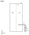
- FIG. 2 is a schematic view showing the overall structure of the housing 10 of the inspection device 1.
- a tube T1 for connecting to the vial bin 12 extends from the housing 10 of the inspection device 1.
- the UV light source 20, the conductivity meter 30, and the pump P described with reference to FIG. 1 are arranged in the housing 10. The method of arrangement will be described later.
- the inside of the housing 10 is separated by a wall portion 14 into a water section A1 that handles the sample water S and an electric section A2 that does not handle the sample water S.
- a flow path F is arranged in the water section A1.
- the electric section A2 a device to be protected from water is arranged.
- a board on which a circuit is mounted, a power system, and the like are arranged in the electric section A2.
- the substrate on which the circuit is mounted is protected from water. You can protect your data.
- the surface of the wall portion 14 is the YZ surface, and the axis orthogonal to each of the Y axis and the Z axis is the X axis.
- FIG. 3 is a schematic view showing the first surface 142 of the wall portion 14 on the water section A1 side.
- a UV light source 20, a pump P, and a measuring unit 32 of a conductivity meter 30 are attached to the first surface 142 in the housing 10.
- Each device attached to the first surface 142 is connected to each other via a tube.
- the tube T1 is connected to the upstream side of the UV light source 20. Although not shown, the tube T1 is connected to the vial bin 12.
- the tube T2 is connected to the upstream side of the UV light source 20.
- the tube T2 functions as a cooling unit.
- at least a part of the tube T2 is made of a material having a higher thermal conductivity than other tubes.
- Oxidation heat is generated when the organic matter in the sample water S is oxidized.
- the conductivity changes as the temperature changes. Therefore, it is necessary to release the heat of oxidation generated before the sample water S is measured by the conductivity meter 30.
- highly accurate conductivity measurement can be performed.
- the measuring unit 32 of the conductivity meter 30 is connected to the downstream side of the tube T2.
- the conductivity meter 30 is a substrate 34 (FIG. 4) on which a measuring unit 32 having a pair of electrodes 324 (see FIG. 6) in contact with the sample water S and a circuit 342 for processing information output from the measuring unit 32 are mounted. See) and.
- the circuit 342 performs, for example, a process (A / D conversion process) of converting analog information output from the measurement unit into digital information.
- the circuit 342 may include a calculation circuit or the like that performs a process of calculating a measured value based on digital information.
- the measuring unit 32 is arranged on the water section A1 side in the housing 10.
- the substrate 34 is arranged on the electric compartment A2 side in the housing 10.
- a flow path is formed inside the measurement unit 32, and the flow path inside the measurement unit 32 is connected to the tube T2 and the tube T3. As described above, the parts through which the sample water S passes are arranged in the water section A1.
- the conductivity meter 30 may be any as long as it measures an index indicating the conductivity of the sample water, and is not limited to measuring the conductivity.
- the conductivity meter 30 may measure the resistivity.
- the conductivity meter 30 has a pair of electrodes 324 and measures the conductivity of the sample water by the two-terminal method, but other methods such as the four-probe method and the four-terminal method are used.
- the conductivity of the sample water may be measured by the method. That is, the conductivity meter 30 may be provided with an electrode portion arranged so as to be in contact with the sample water for measuring an index indicating the conductivity of the sample water, and the electrode portion is composed of two electrodes. It may be configured with four electrodes.
- FIG. 4 is a schematic view showing a second surface 144 of the wall portion 14 on the electric compartment A2 side.
- a cover 102 is attached to the back surface of the housing 10, and a wall portion is further arranged between the cover 102 and the wall portion 14.
- a substrate 34 on which the circuit 342 is mounted is mounted on the second surface 144. Further, a power supply device 50 is arranged in the electric section A2.
- the circuit 342 and the power supply device 50 may cause a malfunction.
- the inside of the housing 10 is separated by a wall portion 14 between the water section A1 that handles the sample water S and the electric section A2 that does not handle the sample water S, and if it gets wet with water such as the circuit 342 and the power supply device 50, it breaks down.
- the device By arranging the device to be stored in the electric section A2, it is possible to provide the inspection device 1 which is less likely to break down.
- the conductivity meter 30 includes a measuring unit 32 arranged on the water section A1 side and a substrate 34 (see FIG. 9) arranged on the electric section A2 side.
- a measuring unit 32 arranged on the water section A1 side
- a substrate 34 arranged on the electric section A2 side.
- FIG. 5 is a front view of the measuring unit 32.
- FIG. 6 is a schematic cross-sectional view taken along the VI-VI line in FIG.
- the front view of the measuring unit 32 shown in FIG. 5 is a front view of the surface facing the first surface 142 when the measuring unit 32 is attached to the first surface 142.
- some configurations such as screws and connecting portions 327 and 328 are omitted.
- the measuring unit 32 includes two openings 323, two electrode contacts 324a, two thermistor contacts 326a, and connecting portions 327,328.
- the opening 323 has a shape in which the columnar connecting portion 343 included in the substrate 34 can be inserted (see FIG. 8).
- Each of the two openings 323 is formed in the housing of the measuring unit 32, and is provided at a position corresponding to the two connecting portions 343 included in the substrate 34.
- the electrode contact 324a is a contact of the electrode 324 shown in FIG. As shown in FIG. 6, the electrode 324 is formed so as to penetrate the flow path F formed in the measuring unit 32. As a result, when the sample water S flows through the flow path F, the sample water S comes into contact with at least a part of the electrode 324. Although only the electrode 324 on one side is shown in FIG. 6, the other electrode 324 is also formed so as to penetrate the flow path F formed in the measuring unit 32.
- the two thermistor contacts 326a are each electrically connected to the thermistor 326 shown in FIG. 6 arranged on the flow path F formed in the measuring unit 32.
- the thermistor 326 measures the temperature of the sample water S passing through the flow path F formed in the measuring unit 32. Conductivity is affected by temperature. Since the conductivity meter 30 is provided with the thermistor 326, the temperature of the sample water S can be measured, so that the conductivity can be accurately measured.
- the connecting portions 327 and 328 are configured to be connectable to the tube T2 and the tube T3, respectively. By connecting the tube T2 and the tube T3 to the connecting portions 327 and 328, the sample water S flows into the flow path F in the measuring portion 32.
- FIG. 7 is a schematic view showing the first surface 142 in a state where the measuring unit 32 is removed.
- FIG. 8 is a diagram for explaining a method of connecting the measuring unit 32 and the substrate 34.
- FIG. 9 is a diagram showing a state when the measuring unit 32 and the substrate 34 are connected.
- an opening 146 is formed in the wall portion 14.
- a packing 148 is provided on the first surface 142, which is the outer periphery of the opening 146. Further, the opening 146 is smaller than the measuring unit 32 and the substrate 34, and the measuring unit 32 and the substrate 34 are electrically connected via the opening 146 with the wall portion 14 interposed therebetween.
- the substrate 34 is arranged on the electric compartment A2 side.
- the substrate 34 is for electrically connecting the thermistor 326 and the circuit 342 with a pair of electrode contacts 344 for electrically connecting the electrodes 324 and the circuit 342. It comprises a pair of thermistor contacts 346 and two connecting portions 343.
- the substrate 34 is arranged on the second surface 144 so that the electrode contact 344 and the thermistor contact 346 are located at the opening 146.
- the two connecting portions 343 are cylindrical protrusions.
- the two connecting portions 343 are formed on the surface on which the electrode contacts 344 are arranged so as to project toward the water compartment A1 side through the opening 146 when the substrate 34 is arranged on the second surface 144.
- connection unit 343 is inserted into the opening 323 of the measurement unit 32 when the measurement unit 32 is arranged on the first surface 142, and connects the measurement unit 32 and the substrate 34. That is, the opening 323 of the measurement unit 32 and the connection unit 343 of the substrate 34 function as a connection unit for connecting the measurement unit 32 and the substrate 34.
- connection portion 343 when the connection portion 343 is inserted into the opening 323 to connect the measurement unit 32 and the substrate 34, the electrode contact 324a of the measurement unit 32 and the electrode contact 344 of the substrate 34 come into contact with each other. As a result, the electrode 324 and the circuit 342 are electrically connected.
- the connection portion 343 when the connection portion 343 is inserted into the opening 323 to connect the measurement unit 32 and the substrate 34, the thermistor contact 326a of the measurement unit 32 and the thermistor contact 346 of the substrate 34 come into contact with each other, resulting in contact.
- the thermistor 326 and the circuit 342 are electrically connected.
- FIG. 9 the description of the configuration of the connection portion 343, the opening portion 323, and the like is omitted.
- the electrode contact 324a of the measuring unit 32 and the electrode contact 344 of the substrate 34 are gold-plated in order to reduce the contact resistance.
- the thermistor contact 326a of the measuring unit 32 and the thermistor contact 346 of the substrate 34 are preferably gold-plated in order to reduce contact resistance.
- the measuring portion 32 of the conductivity meter 30 and the substrate 34 are connected with the wall portion 14 sandwiched between them, and the electrode contact 324a of the electrode 324 and the electrode contact 344 of the substrate 34 are connected to each other. It is arranged so as to be located at the opening 146 of 14.
- the electrode 324 (more accurately, the electrode contact 324a) and the electrode contact 344 of the substrate 34 can be brought into direct contact with each other, and the information output from the measuring unit 32 (for example, analog information which is a detected value) is generated as noise. It can be sent to the circuit 342 of the board 34 so that it does not get stuck. Further, since the electronic devices such as the substrate 34 are arranged in the electric section A2 separated from the water section A1 by the wall portion 14, they can be protected from the sample water S.
- the packing 148 is arranged between the measuring unit 32 and the first surface 142, it is possible to prevent water from entering the electric compartment A2 side from the gap between the measuring unit 32 and the first surface 142.
- the waterproofness of the electric compartment A2 side can be enhanced.
- the packing 148 may be any seal as long as it can prevent water from entering the electric compartment A2 side from the gap between the measuring unit 32 and the first surface 142, and may be a gasket or the like.
- the material of the packing 148 may be any material as long as it is resistant to the sample to be measured by the inspection device 1, and may be appropriately selected depending on the measurement target. Further, although the packing 148 is said to be arranged on the first surface 142, it may be arranged on the measuring unit 32.
- the inspection device 1 is a device for measuring the TOC amount in the sample water.
- the conductivity meter 30 described in this embodiment has a different configuration from the inspection device 1 shown in the above embodiment if it is an inspection device having a configuration in which it is arranged on a flow path through which sample water (liquid sample) flows. It can also be applied to the inspection equipment of. For example, the conductivity meter 30 can be applied to an inspection device that does not have a UV light source 20.
- the measuring unit 32 and the substrate 34 are connected by inserting the connecting unit 343 into the opening 323 with the wall portion 14 sandwiched between the measuring unit 32 and the substrate 34.
- the conductivity meter 30 was fixed to the wall portion 14.
- the measuring unit 32 and the substrate 34 may be individually fixed to the wall unit 14. In the case of a configuration in which the conductivity meter 30 is fixed to the wall portion 14 by connecting the measuring unit 32 and the substrate 34, there is an advantage that the number of parts can be reduced.
- the inspection device for inspecting the sample water includes a housing, a wall portion having an opening that separates the inside of the housing into a first section and a second section, and a first.
- a conductivity meter for measuring the conductivity of the sample water and an inflow pipe for flowing the sample water into the conductivity meter are provided in the compartment.
- the conductivity meter includes a measuring unit having an electrode unit arranged so as to be in contact with sample water, and a substrate on which a circuit for processing information output from the measuring unit is mounted.
- the measuring unit and the substrate are connected with the wall portion interposed therebetween.
- the measuring portion is arranged on the first surface of the wall portion on the first section side so that the electrode portion is located at the opening.
- the substrate is arranged on the second surface of the wall portion on the second compartment side so that the contact point for electrically connecting the electrode portion and the circuit is located at the opening.
- the substrate is arranged in the first section in which the measuring section having the electrode section arranged so as to be in contact with the sample water is arranged and the second section separated by the wall portion. Therefore, the substrate can be protected from the sample water. Furthermore, since the electrode portion and the contact point of the substrate are connected via the opening of the wall portion, the distance from the electrode portion to the circuit can be shortened, and as a result, the information output from the measurement portion is noisy. It can be sent to the circuit so that it does not get stuck.
- the inspection device further includes a seal arranged between the wall portion and the measurement portion, which is the outer periphery of the opening on the first surface.
- the inspection device described in the second section it is possible to prevent water from entering the second compartment side from between the wall portion and the measurement portion, so that the waterproofness of the second compartment side on which the substrate is arranged is enhanced. Can be done.
- the inspection device since the contact resistance between the contact of the substrate and the contact of the electrode portion can be reduced, it is possible to prevent noise from being added to the information output from the measurement unit. ..
- the measuring unit further includes a temperature sensor for measuring the temperature of the sample water.
- the contacts of the temperature sensor are arranged so as to be located at the opening when the measuring unit is arranged on the first surface.
- the contacts of the substrate that electrically connect the contacts of the temperature sensor and the circuit are arranged so as to be located at the opening when the substrate is arranged on the second surface.
- the conductivity affected by the temperature can be measured more accurately. Further, since the contact of the temperature sensor and the contact of the substrate are connected through the opening of the wall portion, the distance from the temperature sensor to the circuit can be shortened, and as a result, the information output from the temperature sensor can be shortened. Can be sent to the circuit without noise.
- the conductivity meter further includes a connection part for connecting the measurement part and the substrate.
- the conductivity meter for measuring the conductivity of the sample water processes the measuring unit including the electrode unit arranged so as to be in contact with the sample water and the information output from the measuring unit. It includes a board on which a circuit is mounted.
- the measuring unit and the substrate are connected with a wall portion that separates the inside of the housing into the first section and the second section.
- the measuring portion is arranged on the first surface of the wall portion on the first section side so that the electrode portion is located at the opening provided in the wall portion.
- the substrate is arranged on the second surface of the wall portion on the second compartment side so that the contact point for electrically connecting the electrode portion and the circuit is located at the opening portion.
- the substrate is arranged in the first section where the measuring section having the electrode section arranged so as to be in contact with the sample water is arranged and the second section separated by the wall portion. Therefore, the substrate can be protected from the sample water. Furthermore, since the electrode portion and the contact point of the substrate are connected via the opening of the wall portion, the distance from the electrode portion to the circuit can be shortened, and as a result, the information output from the measurement portion is noisy. It can be sent to the circuit so that it does not get stuck.
- the measuring unit is arranged on the first surface of the wall portion via a seal arranged on the outer periphery of the opening on the first surface.
- the conductivity meter according to the seventh item it is possible to prevent water from entering the second compartment side from between the wall portion and the measurement portion, so that the waterproofness of the second compartment side on which the substrate is arranged is enhanced. be able to.
Landscapes
- Chemical & Material Sciences (AREA)
- Chemical Kinetics & Catalysis (AREA)
- Electrochemistry (AREA)
- Physics & Mathematics (AREA)
- Health & Medical Sciences (AREA)
- Life Sciences & Earth Sciences (AREA)
- Analytical Chemistry (AREA)
- Biochemistry (AREA)
- General Health & Medical Sciences (AREA)
- General Physics & Mathematics (AREA)
- Immunology (AREA)
- Pathology (AREA)
- Investigating Or Analyzing Materials By The Use Of Electric Means (AREA)
- Measurement Of Resistance Or Impedance (AREA)
Priority Applications (4)
| Application Number | Priority Date | Filing Date | Title |
|---|---|---|---|
| EP21857991.0A EP4202428A4 (en) | 2020-08-20 | 2021-05-06 | INSPECTION DEVICE AND CONDUCTIVITY METER |
| CN202180050730.0A CN115885172A (zh) | 2020-08-20 | 2021-05-06 | 检查装置以及电导率计 |
| JP2022543279A JP7371788B2 (ja) | 2020-08-20 | 2021-05-06 | 検査装置および導電率計 |
| US18/041,951 US12196697B2 (en) | 2020-08-20 | 2021-05-06 | Inspection apparatus and conductivity meter |
Applications Claiming Priority (2)
| Application Number | Priority Date | Filing Date | Title |
|---|---|---|---|
| JP2020139350 | 2020-08-20 | ||
| JP2020-139350 | 2020-08-20 |
Publications (1)
| Publication Number | Publication Date |
|---|---|
| WO2022038839A1 true WO2022038839A1 (ja) | 2022-02-24 |
Family
ID=80322845
Family Applications (1)
| Application Number | Title | Priority Date | Filing Date |
|---|---|---|---|
| PCT/JP2021/017326 WO2022038839A1 (ja) | 2020-08-20 | 2021-05-06 | 検査装置および導電率計 |
Country Status (5)
| Country | Link |
|---|---|
| US (1) | US12196697B2 (en]) |
| EP (1) | EP4202428A4 (en]) |
| JP (1) | JP7371788B2 (en]) |
| CN (1) | CN115885172A (en]) |
| WO (1) | WO2022038839A1 (en]) |
Citations (9)
| Publication number | Priority date | Publication date | Assignee | Title |
|---|---|---|---|---|
| JPS6396455U (en]) * | 1986-12-11 | 1988-06-22 | ||
| JPH0256699B2 (en]) | 1982-04-05 | 1990-11-30 | Texas Instruments Inc | |
| JP2000505888A (ja) * | 1996-01-11 | 2000-05-16 | ガンブロ アクチーボラグ | 流体の電気的因子を測定する方法および機器 |
| JP2001281189A (ja) * | 2000-03-30 | 2001-10-10 | Japan Organo Co Ltd | 全有機体炭素の測定方法および装置 |
| US6444474B1 (en) * | 1998-04-22 | 2002-09-03 | Eltron Research, Inc. | Microfluidic system for measurement of total organic carbon |
| JP2008139312A (ja) * | 2006-12-01 | 2008-06-19 | Millipore Corp | 導電率測定装置ならびにその製造および使用 |
| US20120304743A1 (en) * | 2010-02-11 | 2012-12-06 | Hach Company | Carbon quantifying apparatus and method |
| JP2019055404A (ja) * | 2011-01-17 | 2019-04-11 | エヴォクア ウォーター テクノロジーズ エルエルシーEvoqua Water Technologies LLC | 超純水を提供するための方法およびシステム |
| JP2020063916A (ja) * | 2018-10-15 | 2020-04-23 | 国立中山大学National Sun Yat−Sen University | 溶液性質検出用センサ |
Family Cites Families (8)
| Publication number | Priority date | Publication date | Assignee | Title |
|---|---|---|---|---|
| US3991623A (en) * | 1973-10-09 | 1976-11-16 | Westinghouse Electric Corporation | Marine instrument |
| US4626413A (en) * | 1984-01-10 | 1986-12-02 | Anatel Instrument Corporation | Instrument for measurement of the organic carbon content of water |
| US20100034702A1 (en) * | 2007-03-20 | 2010-02-11 | Masakazu Akechi | Total organic carbon measuring instrument |
| EP2803996A1 (fr) | 2013-05-15 | 2014-11-19 | Merck Patent GmbH | Dispositif de mesure de conductivité d'un liquide pour déterminer de très bas niveaux de carbone organique total (TOC) dans de l'eau pure et ultra-pure |
| WO2014205230A1 (en) * | 2013-06-19 | 2014-12-24 | Step Ahead Innovations Inc. | Aquatic environment water parameter testing systems and methods |
| CN206450293U (zh) * | 2017-01-25 | 2017-08-29 | 佛山市申海电子有限公司 | 电容式水位检测电路 |
| JP6401811B2 (ja) * | 2017-03-15 | 2018-10-10 | Kyb株式会社 | 流体性状検出装置 |
| CN108760828B (zh) * | 2018-08-15 | 2023-07-28 | 河北科瑞达仪器科技股份有限公司 | 一种用于液体电导率测量的装置 |
-
2021
- 2021-05-06 EP EP21857991.0A patent/EP4202428A4/en active Pending
- 2021-05-06 WO PCT/JP2021/017326 patent/WO2022038839A1/ja unknown
- 2021-05-06 US US18/041,951 patent/US12196697B2/en active Active
- 2021-05-06 JP JP2022543279A patent/JP7371788B2/ja active Active
- 2021-05-06 CN CN202180050730.0A patent/CN115885172A/zh active Pending
Patent Citations (9)
| Publication number | Priority date | Publication date | Assignee | Title |
|---|---|---|---|---|
| JPH0256699B2 (en]) | 1982-04-05 | 1990-11-30 | Texas Instruments Inc | |
| JPS6396455U (en]) * | 1986-12-11 | 1988-06-22 | ||
| JP2000505888A (ja) * | 1996-01-11 | 2000-05-16 | ガンブロ アクチーボラグ | 流体の電気的因子を測定する方法および機器 |
| US6444474B1 (en) * | 1998-04-22 | 2002-09-03 | Eltron Research, Inc. | Microfluidic system for measurement of total organic carbon |
| JP2001281189A (ja) * | 2000-03-30 | 2001-10-10 | Japan Organo Co Ltd | 全有機体炭素の測定方法および装置 |
| JP2008139312A (ja) * | 2006-12-01 | 2008-06-19 | Millipore Corp | 導電率測定装置ならびにその製造および使用 |
| US20120304743A1 (en) * | 2010-02-11 | 2012-12-06 | Hach Company | Carbon quantifying apparatus and method |
| JP2019055404A (ja) * | 2011-01-17 | 2019-04-11 | エヴォクア ウォーター テクノロジーズ エルエルシーEvoqua Water Technologies LLC | 超純水を提供するための方法およびシステム |
| JP2020063916A (ja) * | 2018-10-15 | 2020-04-23 | 国立中山大学National Sun Yat−Sen University | 溶液性質検出用センサ |
Non-Patent Citations (1)
| Title |
|---|
| See also references of EP4202428A4 |
Also Published As
| Publication number | Publication date |
|---|---|
| US20230314356A1 (en) | 2023-10-05 |
| EP4202428A4 (en) | 2024-10-02 |
| EP4202428A1 (en) | 2023-06-28 |
| US12196697B2 (en) | 2025-01-14 |
| JP7371788B2 (ja) | 2023-10-31 |
| JPWO2022038839A1 (en]) | 2022-02-24 |
| CN115885172A (zh) | 2023-03-31 |
Similar Documents
| Publication | Publication Date | Title |
|---|---|---|
| CN102565137B (zh) | 具有可替换样品收集芯片的化学品传感器 | |
| US6313638B1 (en) | Dual-channel photo-ionization detector that eliminates the effect of ultraviolet intensity on concentration measurements | |
| US7279903B2 (en) | Non-metallic flow-through electrodeless conductivity sensor with leak and temperature detection | |
| US6997043B2 (en) | Integration of atmospheric intrusion sensors in electronic component packages | |
| TW505789B (en) | Multiple electric conductivity measuring apparatus | |
| US10088448B2 (en) | Gas sensor element | |
| CN115047037A (zh) | 一种基于微流控气敏传感器的便携式检测装置及检测方法 | |
| JP2000241382A (ja) | ガスセンサ | |
| KR20100070718A (ko) | 표면전자공명 검출장치 및 검출방법 | |
| CN105247355A (zh) | 用于测量气体混合物的气体组份的导热能力的装置 | |
| JP2019082467A (ja) | 漏液感知システム及び漏液感知方法 | |
| TWI580953B (zh) | 用於偵測於一離子室中煙霧之方法及設備 | |
| WO2022038839A1 (ja) | 検査装置および導電率計 | |
| US20110280281A1 (en) | Temperature Sensor | |
| US20080209987A1 (en) | Measurement Instrument | |
| CN113866248B (zh) | 一种二氧化碳浓度检测传感器的检测方法 | |
| CN113155904B (zh) | 一种用于空气环境中的高灵敏氢气传感器及其制备方法 | |
| CN108139348B (zh) | 制冷剂分析仪及其使用方法 | |
| JP2009063500A (ja) | レベルゲージセンサ | |
| JP5853873B2 (ja) | 濃度検出装置 | |
| JP2001311710A (ja) | 多元電気伝導度測定装置 | |
| CN110793958B (zh) | 一种氢化物发生-大气压辉光放电原子光谱装置 | |
| JP5042166B2 (ja) | 導電率測定装置および導電率測定装置を用いた導電率測定方法 | |
| KR20240096165A (ko) | 통합형 센서 모듈 | |
| CN118871779A (zh) | 气体传感器 |
Legal Events
| Date | Code | Title | Description |
|---|---|---|---|
| 121 | Ep: the epo has been informed by wipo that ep was designated in this application |
Ref document number: 21857991 Country of ref document: EP Kind code of ref document: A1 |
|
| ENP | Entry into the national phase |
Ref document number: 2022543279 Country of ref document: JP Kind code of ref document: A |
|
| NENP | Non-entry into the national phase |
Ref country code: DE |
|
| ENP | Entry into the national phase |
Ref document number: 2021857991 Country of ref document: EP Effective date: 20230320 |